The 10-Point Checklist for Selecting Low Profile Antennas for Vehicle-Mounted RF Systems
Vehicle-mounted RF systems operate under conditions that most fixed-installation equipment never encounters. They face constant vibration, temperature cycling, exposure to weather, and the mechanical stress of daily use across varying terrain. When an antenna fails or performs inconsistently in these environments, the consequences are rarely minor. Communication drops, positioning errors, or signal interference can compromise safety, operational continuity, and mission-critical decision-making.
Selecting the right antenna for a vehicle-mounted application is not simply a matter of matching frequency ranges on a specification sheet. It requires understanding how the antenna will behave across the full operational lifecycle — under load, in motion, in degraded weather, and across the range of environments the vehicle will encounter. This checklist provides a structured framework for making that selection with the level of care the application demands.
1. Understand What Low Profile Actually Means for Your Application
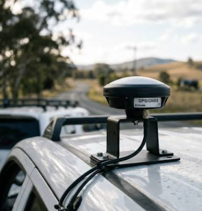
The term “low profile” refers to antennas designed with a reduced physical height and compact form factor, making them suitable for installations where clearance, drag, aesthetics, or structural integrity are limiting factors. For vehicle-mounted systems, this typically means roof-mounted, rail-mounted, or surface-flush configurations that minimize protrusion without sacrificing the RF performance needed for reliable communication.
A good starting point when evaluating your options is to review current product categories for low profile antennas to understand what form factors, frequency bands, and mounting configurations are available before narrowing your specification criteria. The term itself does not imply compromise — in many cases, a well-engineered low profile design outperforms a traditional whip antenna in vehicle environments because it reduces wind load, mechanical resonance, and the risk of physical damage during operation.
Why Form Factor Matters Beyond Aesthetics
In fleet operations, public safety vehicles, or mobile command units, a protruding antenna is not just an aesthetic concern. It introduces mechanical risk — the antenna can be struck by obstacles, damaged during vehicle washing, or stressed repeatedly by wind at highway speeds. Repeated mechanical stress on a tall, rigid antenna degrades the connection point over time, creating intermittent signal issues that are difficult to diagnose. A lower profile reduces that mechanical moment arm, distributing stress more evenly across the mounting surface.
2. Define the Frequency Bands Your System Actually Uses
Every RF system has a defined operating frequency or set of frequencies, and the antenna must be matched to those bands to function correctly. In vehicle-mounted systems, this is often more complex than it appears, because many platforms operate across multiple frequency ranges simultaneously — combining cellular, GPS, public safety radio, Wi-Fi, and satellite links within a single installation.
Multi-Band vs. Single-Band Decisions
A single multi-band antenna may seem like the more efficient choice, but combining too many frequency ranges into one antenna can introduce performance trade-offs across each band. In critical applications, it is worth evaluating whether dedicated single-band antennas for the most essential links would deliver more reliable performance than a consolidated multi-band solution. The right answer depends on available mounting space, coax routing constraints, and the relative importance of each frequency band to mission success.
3. Evaluate the Mounting Environment Before Specifying Hardware
The mounting surface on a vehicle is rarely ideal from an RF perspective. Metal roof panels, fiberglass composites, carbon fiber body panels, and reinforced glass all behave differently as ground planes for antenna systems. The size, conductivity, and geometry of the mounting surface affect radiation pattern, gain, and impedance matching — all of which influence how reliably the antenna performs in the field.
Ground Plane Dependence and Its Practical Implications
Many low profile antenna designs depend on an adequate ground plane to achieve their rated performance. On a standard steel-roof vehicle, this is rarely a problem. On specialty vehicles with non-metallic body panels or constrained mounting areas, the antenna’s effective ground plane may be significantly smaller than the manufacturer’s test conditions assumed. This can lead to reduced gain, altered radiation patterns, or impedance mismatch — all of which degrade signal reliability without producing an obvious point of failure.
4. Confirm Environmental Ratings Match the Operational Context
Vehicle-mounted antennas are exposed to rain, road spray, dust, ice, UV radiation, and thermal cycling across a wide temperature range. The sealing and material quality of the antenna assembly determines whether it maintains consistent electrical performance across that range or degrades over time as moisture ingresses or housing materials fatigue.
What Ingress Protection Ratings Mean in Practice
Ingress protection ratings, as defined by the IEC 60529 standard published by the International Electrotechnical Commission, describe the degree to which an enclosure resists the entry of solid particles and liquids. For vehicle-mounted applications in exposed positions, an IP67 or IP68 rating is generally the appropriate baseline. An IP65 rating, while dust-tight, may not provide adequate protection against the sustained water exposure a roof-mounted antenna encounters during heavy rain or high-pressure vehicle washing.
5. Assess Connector and Cable Routing Requirements
The antenna connector type and the coaxial cable routing path are often treated as afterthoughts, but they are frequently the source of installation problems and long-term reliability failures. A connector that is difficult to weather-seal, a coax bend radius that is too tight for the cable type, or a routing path that exposes the cable to abrasion can introduce more signal loss than a suboptimal antenna selection.
Connector Selection Under Real-World Conditions
In vehicle installations, the antenna connector is subject to vibration, thermal expansion, and repeated incidental contact during vehicle maintenance. Connectors that are not torqued correctly or that use materials prone to galvanic corrosion can develop intermittent resistance at the connection point — a failure mode that causes signal degradation that varies with temperature and movement and is extremely difficult to isolate without systematic testing.
6. Consider the Vibration and Shock Profile of the Vehicle Platform
Different vehicle platforms produce very different vibration profiles. A highway fleet vehicle, an off-road utility truck, a rail inspection vehicle, and a marine vessel each impose different frequencies and amplitudes of mechanical stress on mounted equipment. An antenna selected without reference to the vibration environment may meet all electrical specifications while failing mechanically within months of deployment.
Resonance Frequencies and Mounting Design
When the mechanical resonance frequency of an antenna assembly aligns with the dominant vibration frequency of the vehicle structure, it can produce oscillation that fatigues the mounting base or internal connections over time. This is particularly relevant for antennas mounted near the vehicle’s suspension system or on platforms with diesel powertrains, which produce distinctive low-frequency vibration profiles. Reviewing manufacturer test data for vibration and shock compliance is a necessary step before finalizing selection.
7. Clarify Integration Requirements with Existing RF Infrastructure
In most vehicle-mounted applications, the antenna is not a standalone component — it feeds into a larger RF infrastructure that includes amplifiers, splitters, combiners, and radio units. Impedance mismatches, connector compatibility issues, and cable loss calculations must all be considered as part of the full system integration, not just the antenna selection in isolation.
System-Level Signal Budget Planning
Every component in the RF chain introduces some amount of signal loss. The antenna’s gain specification, the coax cable loss at operating frequency, the insertion loss of any passive components, and the sensitivity of the radio receiver together define the overall link budget. Selecting an antenna without accounting for the full signal path can result in a system that meets specifications on paper but performs poorly in the field, particularly at the edges of the intended coverage area.
8. Review Regulatory Compliance Requirements for Your Operating Region
Vehicle-mounted RF systems operating in commercial, public safety, or government contexts are subject to type acceptance requirements and operational regulations that vary by country and frequency band. Using a non-compliant antenna — even unintentionally — can expose the operator to regulatory risk and, in some cases, void the type acceptance of the radio equipment to which it is connected.
Type Acceptance and Antenna Substitution Rules
In many regulatory frameworks, substituting an antenna that was not part of the original type-accepted radio configuration requires verification that the substituted antenna does not cause the system to exceed authorized power limits or spurious emission thresholds. This is a commonly overlooked compliance risk, particularly in fleet environments where antennas may be replaced as maintenance items without reference to the original radio authorization documentation.
9. Evaluate Supplier Documentation and Long-Term Parts Availability
For fleet operators or organizations deploying RF systems at scale, the supplier’s ability to provide consistent product quality, complete technical documentation, and long-term parts availability matters as much as the antenna’s initial performance specifications. An antenna that performs well but becomes unavailable within two years of deployment creates a compatibility management problem that can be disproportionately costly to resolve.
Technical Documentation as a Quality Indicator
The quality of a manufacturer’s technical documentation — installation instructions, test reports, dimensional drawings, and environmental test certifications — is a reliable indirect indicator of the organization’s overall engineering discipline. Suppliers who invest in thorough documentation are generally those who also invest in consistent manufacturing quality and meaningful product validation. This matters in operational environments where field maintenance is performed by technicians rather than RF engineers.
10. Validate Performance Through Field Testing Before Full Deployment
Specification sheets describe performance under controlled test conditions that rarely replicate the operational environment of a vehicle-mounted system. Before committing to a full deployment, field validation testing in a representative operational context provides the most reliable basis for a final selection decision.
See also: How a Business Attorney Greenville SC Can Help Your Business
What Field Testing Should Actually Measure
Effective field testing goes beyond confirming that the antenna connects and the radio operates. It should include signal strength measurements across the expected coverage area, performance evaluation under adverse weather conditions, and a review of how the antenna affects adjacent systems through interference or pattern distortion. Testing conducted over a representative operational period — including vehicle movement across terrain typical of the deployment context — gives the most accurate picture of real-world reliability.
Closing Considerations
Selecting a vehicle-mounted antenna for an RF system is a decision that carries long-term consequences for system reliability, maintenance burden, and operational continuity. The ten areas covered in this checklist are not independent criteria — they interact. A good frequency match matters less if the environmental sealing is inadequate. Excellent mechanical durability is of limited value if the system-level signal budget has not been properly planned.
The most consistently reliable vehicle RF installations result from treating antenna selection as a systems engineering exercise rather than a procurement task. That means engaging with the full operational context early, documenting requirements clearly, and validating assumptions through field evidence before scaling deployment. Done carefully, this process reduces the risk of in-service failures, simplifies maintenance planning, and produces RF systems that perform consistently across the full operational life of the vehicle platform they serve.